
Vertical Power 400/400DUO
 |
| The VP-400 finds the best airport to land then flies your airplane to the runway threshold. Know instantly what your options are. The Vertical Power VP-400 is a next-generation backup EFIS that complements today’s primary EFIS products and incorporates its own independent solid-state gyros, and GPS receiver, as well as the electronic circuit breaker system with the VP-400. |
| VP-400 in 30 Seconds Video |
| VP-400 Overview The Vertical Power VP-400 is a back-up EFIS that flies your aircraft safely to the best runway in an emergency. The best airport is the one with the longest and widest runway that is pointed most directly into the wind that you can still safely glide to without impacting terrain or obstacles. THAT is the airport you want to glide to in an emergency! Your existing GPS nearest function understands none of these things. The VP-400 integrates several leading-edge technologies that together enable a new level of safety and peace-of-mind for pilots. The enabling technologies are:
|
 The VP-400 was developed in partnership with Laminar Research, makers of the X-Plane engineering flight simulator. By combining Vertical Power’s expertise in avionics with Laminar Research’s expertise in advanced flight modeling and synthetic vision imagery, new capabilities are available to make flying safer and easier. The VP-400 was developed in partnership with Laminar Research, makers of the X-Plane engineering flight simulator. By combining Vertical Power’s expertise in avionics with Laminar Research’s expertise in advanced flight modeling and synthetic vision imagery, new capabilities are available to make flying safer and easier. |
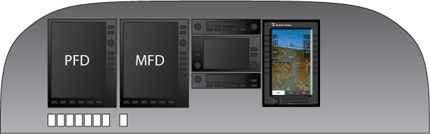 |
| VP-400 is complementary to the primary EFIS |
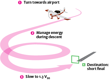
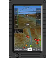
| Simple To Use! When there is an emergency, simply pull the throttle to idle and press the Runway Seeker button on your instrument panel. VP-400 The system automatically engages the autopilot to fly the glide path to the runway, leaving you free to focus on emergency procedures and talk to controllers. It sets the correct airspeed and even controls your flaps to manage energy during the descent so you arrive at the runway threshold on-speed, on-heading, on-altitude, and ready to land. Descent paths are calculated to be clear of known terrain and obstacles. When over the threshold, manually disconnect the Runway Seeker and land the airplane. The Runway Seeker is for emergency use only, and should not be used in place of normal published instrument approaches or VFR traffic pattern procedures. The Runway Seeker is for emergency use only, and should not be used in place of normal published instrument approaches or VFR traffic pattern procedures. The diagram below outlines how the VP-400 works once the Runway Seeker is engaged. |
 |
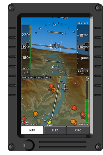
| Display Optimized for Emergency Glide Descent The VP-400 display is intentionally uncluttered to show the information you need to make a safe emergency descent and landing. The VP-400 display shows: |
|
|
 |
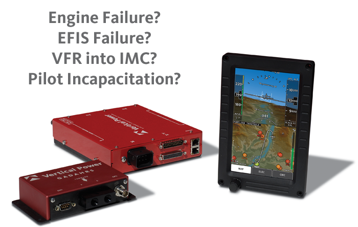
| System Components |
 |
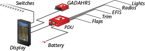
Display The display mounts in your instrument panel and displays the synthetic vision view, map view, electrical system view, and a list of electrical device including device status and individual current draw. Using the touch screen, you can turn devices on and off including flaps and trim (in addition to normal switches). User-configured annunciators for things like canopy or door alarms are also shown. The screen is a high-resolution display (600×1024 pixels) with a bright 1000-nit LED backlight. The built-in back-up battery provides 30+ minutes of power to the display in case of an electrical system failure. |
 |
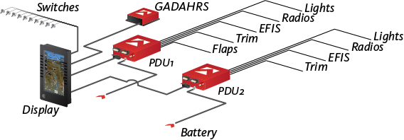
GADAHRS The system includes an independent self-contained GPS, air data, attitude, heading reference system (GADAHRS). The solid state gyro and software is licensed from Cloud Cap Technology (a wholly owned subsidiary of the Goodrich Corporation) that uses it in certified instruments as part of both aircraft and unmanned vehicles. The GPS is a highly-accurate WAAS GPS receiver that provides exceptional vertical accuracy. |
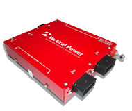 |
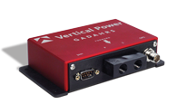
PDU (VP-400 only) The Power Distribution Unit houses solid-state electronic circuit breakers and trim/flap controllers for protection and management of the electrical system on your aircraft. It turns electrical devices on and off, runs the trim and flap motors, handles short circuits, and watches for overvoltage and under-voltage conditions. Vertical Power’s DualBuss™ Technology provides two independent power banks (from a single power source) in a single enclosure, delivering unprecedented levels of redundancy and safety. Builders can now easily divide avionics and other electrical loads between two power busses, and should one bus controller fail the other bus will continue to operate independently and be able to provide power to the starter contactor. Each bus controller is powered by an independent power supply and microprocessor. |
| VP-400 System The VP-400 system includes a display and GADAHRS (GPS, air data, attitude, heading reference system), and one power distribution unit (PDU). |
 |
| VP-400 Duo System The VP-400 Duo system includes a display and GADAHRS (GPS, air data, attitude, heading reference system), and two power distribution unit (PDU). The Duo is recommended for true dual-independent bus electrical architecture (two batteries, two master contactors, two independent alternators, and a cross tie contactor) or a single bus architecture that needs more circuits than a single PDU can provide. |
 |
| Specifications |
| Power | 6-32 volts DC; Dual diaode-isolated power inputs |
| Battery Backup | Built in, user replaceable. 30+ minutes power for display and GADAHRS only |
| Weight | Display 2.6 lbs; PDU 2.1 lbs (VP-400 only); GADAHRS 0.7 lbs |
| Mounting | Display - mounts from front of panel with four 6-32 screws PDU - mounts with included bracket or optional mounting try (VP-400 only) GADAHRS - mounts with four 10-32 non-ferrous screws/nuts |
| Connectors | Display - two 25 pin d-sub connectors, two 50 pin d-sub connectors PDU - three power connectors, two 25 pin d-sub connectors (VP-400 only) GADAHRS - one 9 pin d-sub connector |
| Operating Temperature | -40 to +85 deg C |
| Certification | The VP-400 is for use with experimental and light sport aircraft only |
| Detailed dimension drawing here |
11 years ago